Introduction
The purpose of a sound converter is to convert a electrical music signal into sound waves. A single loudspeaker would be ideal for this, if it can transfer the electrical signal correctly by means of phase and magnitude. Furthermore this loudspeaker needs to be able to have a large enough membrane surface to produce low frequencies efficiently, but the membrane needs to be very light to reproduce high frequencies as well.
These conditions are in conflict, obviously. Thus one has to select multiple drivers to reach the best quality of audio reproduction. It makes sense to go for the specialists in their area: for low frequencies a large membrane surface with a higher mass is ideal. For medium and high frequencies very light and rigid calottes are to be chosen. The real challenge is to combine all those drivers in this multiple-way-loudspeaker constellation with a cross-over section so that the individual frequency responses sum up correctly by means of phase and magnitude.
So the underlying or principal problem of a good loudspeaker design is the displacement of the acoustical centers of the used drivers together with unavoidable phase turns caused by the classical cross-over filters.
Concept
Firs of all, all acoustical places of origin (the acoustical centers) from high, mid and low-range drivers must have the same distance to the ear at the listening position. The human ear only evaluates the first millisecond of perceived sound to locate the source. If the signal is deformed in this fist millisecond, the ear fails to explicitly locate the source. The stereoscopic exposure is experienced as diffuse. The only way to prevent cancellation in this critical time frame (the transient oscillation phase) is to mechanical align the acoustical centers of the drivers. Furthermore the take-over between two drivers should ideally happen without phase differences. But since every filter not only creates a frequency band but also the corresponding phase levelling, one can just try to approximate these demands as good as possible. The term "phase" must not be confound with time in this context, which the two following examples will show:
1. By using a "alpass-circuit", one can turn the signal by -180° to turn back the +180° advanced phase of the high pass. However, the amplitude of the signal is still half a period ahead, just with switched sign. So it does not correspond the amplitude of the original signal at the examined time.
2. A phase difference between low- and high-pass of 360°, 720°, ... is often interpreted as "perfect" overlay. This, however, only holds true when periodic signals are used, where every period of the signal is identical (i.e. a sinus). Music signals, of course, are rather rarely periodic - in contrast, they change constantly. Consider the time delay corresponding to the 360° phase difference, one can clearly understand that the two signals will not sum up correctly. The signal from the low- or midrange driver is added with the signal from the tweeter which is one period ahead! The resulting sum is not correct.
Conventional filters of second or higher order manifest almost always such a phase difference / phase delay. As far as we know, also with digital FIR filters it is not possible to equalize the real run-time of the filtered signals. The error can easily be seen in the step response.
Thus it can be said that a new filter design or filter function is required which enables very low phase shifts between the drivers. Furthermore the filters need to be designed so that the cross-over frequencies (which is where the phase differences would be the most noticeable) are placed in areas, where the human ear is not as sensitive. Thus resulting phase distortions would be covered by masking effects and thus lie below the threshold of audibility.
The drivers
The required filters are depended on the perfect interplay between the electrical circuit and the acoustic behavior of the drivers. Therefore the drivers have to fulfill the following requirements:
The inductivity of the voice coil has to be very low in conjunction with a low electronical quality factor and low natural resonance. This can be best archived with powerful and long-stroke lower slope magnet-systems. Additionally the membranes have to be light, stiff and rigid so that no deformation energy is picked-up, which can lead to signal deficits at the swing-in stage. Also the resonance behavior of the membrane hast to cater for the aimed frequency response.
Evaluation
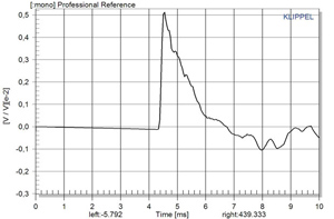
The correct transmission of the full frequency band of a loudspeaker can be analyzed by looking at the step-response and the frequency response. The step response already carries all information about the interplay between the drivers. In the case of our surrounTec™ products all requirements are fulfilled:
1. All acoustical centers are placed on an arch with mechanical time-alignment
2. The single frequency responses of the drivers sum-up correctly to a smooth combined frequency response without breakouts
3. The phase is connects smoothly at the cross-over frequencies. The result is a linear acoustical phase
4. The membrane resonances are removed by filters without affecting the phase negatively
In consequence we are happy to say that all surrounTec™ passive loudspeaker systems show a good approximation of the theoretical ideal and a close to perfect step response.


